Induced and Dissolved Gas Flotation: A Review of Principles and Applications for Produced Water Treatment
Produced water, a significant byproduct generated during oil extraction, represents the largest waste stream in the petroleum sector. While a considerable portion of this water is still released into the ocean, some facilities opt to re-inject it back into reservoirs to maintain pressure or for disposal purposes. Gas flotation is a separation technique extensively applied both onshore and offshore, typically capable of reducing oil concentrations below 25 ppmv. It also holds great potential for subsea water treatment applications.
Gas flotation can be categorized into three primary types: induced gas flotation (IGF), dissolved gas flotation (DGF), and electroflotation. This discussion will focus on the first two, which are commonly used in oil field operations. The key distinction between IGF and DGF lies in their methods of bubble generation, which in turn affects bubble size, mixing intensity, hydraulic loading rate, and retention time.
Induced Gas Flotation (IGF)
In induced gas flotation systems, gas bubbles are introduced into the wastewater either through mechanical or hydraulic means. Mechanical IGF utilizes an impeller to generate flow eddies that disperse gas into the water. In contrast, hydraulic IGF employs an eductor to draw gas into the liquid, offering the advantage of fewer moving components. Bubbles created via IGF typically range from 100 to 1000 μm in diameter (19). A schematic of a hydraulic IGF system is shown in Figure 1. Modern offshore flotation systems often adopt a compact, vertically oriented hydraulic IGF design that operates without moving parts.
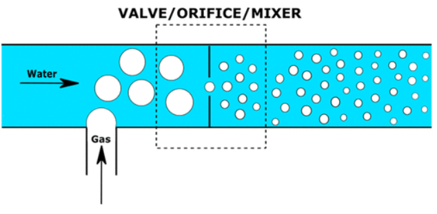
Figure 1. Illustration of hydraulic IGF
Dissolved Gas Flotation (DGF)
Dissolved gas flotation relies on the release of fine bubbles formed when pressure is reduced, allowing dissolved gas in both water and oil to nucleate and grow. Nucleation in supersaturated liquid may occur homogeneously or heterogeneously, with the latter being more efficient due to lower energy barriers when nucleation takes place on existing surfaces. Another important aspect of DGF is the higher solubility of gas in oil compared to water. As a result, more gas is released from oil droplets during depressurization than from the surrounding aqueous phase. Thus, the expansion of gas bubbles within oil droplets is a relevant factor in DGF processes. The bubbles generated in DGF are notably smaller than those in IGF, with diameters between 10 and 100 μm. Due to their smaller size, retention times are generally longer. The gas-to-oil ratio and hydraulic loading rate are also critical parameters in DGF performance.
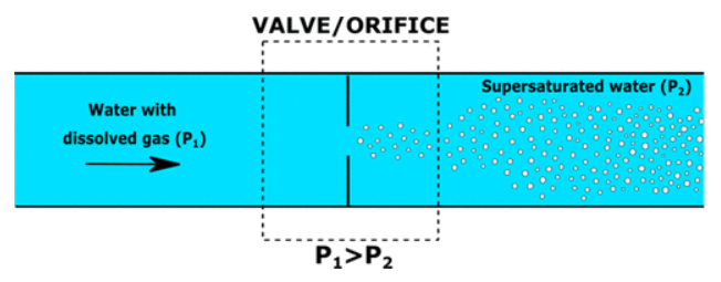
Figure 2. Illustration of bubble generation during DGF
Recent research has explored the role of nanoscale bubbles in DGF. Evidence suggests that these tiny bubbles can attach to or become trapped within oil droplets, forming capillary bridges between them. This enhances droplet hydrophobicity and improves their adhesion to microbubbles, thereby increasing the overall efficiency of the flotation process.
Flotation Principle
The relative sizes of oil droplets and gas bubbles significantly influence the mechanisms of oil removal during flotation. The size distributions of both components are central to determining flotation efficiency. Research indicates that collision efficiency depends on the dimensions of both bubbles and oil droplets. Using smaller gas bubbles has been shown to enhance oil removal, which is attributed to the increased surface area available for droplet attachment. Smaller bubbles also raise the frequency of collisions, a key factor in capturing oil droplets. In contrast, larger bubbles tend to reduce collision efficiency.
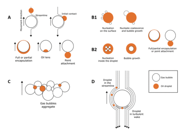
Figure 3. Mechanisms for gas bubble capture of oil droplets suspended in water
Additionally, studies report that as bubble size increases, oil attachment efficiency declines due to a reduction in the contact angle. It should be noted that gas bubbles are generally larger than oil droplets. Flotation is most effective for droplets larger than 20 μm; smaller droplets may require excessively long retention times. Since produced water treated in gas flotation units has usually undergone primary treatment, most remaining oil droplets are smaller than 20 μm. When such small droplets are difficult to separate, flocculants may be introduced to enhance oil removal efficiency.